Control of the mobile robot using controllers of types P, PI, PID
Dorian Skrobek
,Dawid Cekus
,Tomasz Zając
Journal of Applied Mathematics and Computational Mechanics |
 Download Full Text |
CONTROL OF THE MOBILE ROBOT USING CONTROLLERS OF TYPES P, PI, PID
Dorian Skrobek 1, Dawid Cekus 1, Tomasz Zając 2
1
Institute of Mechanics and Machine Design Fundamentals, Czestochowa University
of Technology
Czestochowa, Poland
2 Kimla, ul. Bałtycka 30, Czestochowa, Poland
skrobek@imipkm.pcz.pl, cekus@imipkm.pcz.pl, tomasz.zajac@gmail.com
Received: 8 February 2018;
Accepted: 15 March 2018
Abstract. The paper presents a method for control of a mobile robot. The task of the Line-follower was to cover the route set programmatically as accurately as possible using the controllers P, PI or PID without the use of sensors to detect the line. The work also consists of a description of the mobile robot development and the results of the experimental research with discussion.
MSC 2010: 62Q05, 65G99, 93C95, 93C85
Keywords: line-follower, mobile robot, controller P, PI, PID
1. Introduction
In the industry, line-follower robots are used mainly in controlled transport of waste or to deliver materials to workplaces. The two main methods exist [1] to control such robots:
· limited sequence robot - it is the most elementary type of control and can be applied to a simple motion in which the accuracy of the trajectory mapping and the reaching of the target is not taken into account,
· playback robot with point to point type (PTP) - in this type of control, great emphasis is placed on accurate trajectory mapping. A control system quickly makes necessary changes in the program.
The various types of controllers are applied to control the drive of the line-fol- lower along the designated path. Regulators can be divided according to the type of used energy:
· direct action regulators (oldest);
· regulators using auxiliary energy: electric, pneumatic, hydraulic,
or because of the form of the output signal:
· regulators with a discontinuous output signal (on-off) are typically electric regulators,
· on-off controllers with correction,
· controllers with a continuous output signal (P, PI, PD, PID), electrical (analog or digital), pneumatic and hydraulic,
· fuzzy controllers - regulators based on fuzzy logic. They analyze analog input values in terms of logic variables that take continuous values from 0 to 1. These controllers in the line-followers perfectly match the trajectories, but overcome it in a much larger time than in the case of continuous regulators [2],
· regulators based on artificial intelligence (AI-based controllers), require learning,
· model-based controllers (MBC) - used in control systems, where regulators must be each time adapted to changes in the properties of the object [3].
The continuous regulators [4-7] are the basis for the tested control algorithms in mobile robots.
The main goal of the project was to prepare the structure and program for the robot competition. The fully autonomous robot has to overcome the route determined with the help of a piece of black tape on a white foundation as quickly and as accurately as possible.
The underling research tries to investigate the characteristics of a certain kind of controllers with a continuous output. The research is based on a single application - a line-following robot. The research is therefore trying to contribute to the scientific community be providing an in-depth comparison.
Line-followers are a small (usually the size of these robots does not exceed the size A4) and fast structures whose task is traversing the route in the shortest possible time. These robots, using optical sensors, move on a white ground with an outlined black route (or vice versa).
In the paper, the existing Line-follower [8, 9] has been exploited to present the control system of the mobile robot. The control algorithm enables motion of the robot along the track set programmatically without using the sensors to detect the line. The robot has to cover the route with the greatest accuracy using the controller P, PI or PID. The research presented in this article aims to show differences in the control of the mobile robot depending on the regulator used. The values of the proportioning, integrating and derivative element were selected using the manual setting method.
2. Research object
The Line-follower presented in the paper [4] (Fig. 1a) has been modified in order to develop the control system. The development of the mobile robot consisted in an expansion of two encoders equipped with a slotted optocoupler TCST1103 that cooperate with disks with eighteen slots cut. A cyclic covering and uncovering of a slot is performed while a wheel rotates. A covering of the slot of the optocoupler results in blocking out a light coming to the base, which stops the flow of the current to the emitter, however, uncovering makes the current to flow. The disk of the encoder is fixed to a bushing mounted onto a rim. Exploited encoders are one-channel encoders and can only count the impulses. The definition of a direction of an engine revolutions is directly impossible [10-12].

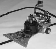
Fig. 1. Line-follower (on the left), modified mobile robot (on the right)
Additionally, microcontroller ATmega8A that is intended for operating encoders and transmitting control signals to a previously-mounted microcontroller ATmega644P that controls the engine operation has been installed. A modified research object is shown in Figure 1b.
Due to the fact that two microcontrollers have been installed [13, 14], the control program has been divided into two programs:
· Master control program, whose memory the track of the robot race is saved in, is located on the microcontroller ATmega8A. The task of the program is to control a turbine that increases the tractive adhesion of the robot while racing to determine the value of a rotational speed of engines and transmit this information to the other microcontroller.
· Slave program (engine running controller) that is performed at microcontroller ATmega644P. The program controls engine running by means of bridge H on the basis of outputs.
Programs have been written in C++ by taking advantage of Arduino programming environment. The scheme of the control system action is presented in Figure 2. Depending on the program configuration, the controller is able to run as a controller of types: P, PI or PID [5-7, 15].
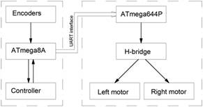
Fig. 2. The principle of the program action
3. Sample experimental research
Sample experimental research has been carried out on the track presented in the Figure 3. This track consists of three straight lines and two arcs. The first line has length L1 = 1 m, then converts to right arc with an angle equalling 90° and radius R = 0.3 m, next there is another straight line with length L2 = 0.25 m, which converts to left arc and consecutively there is last straight line with length L2 .
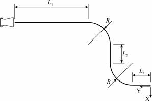
Fig. 3. Race track
Because the aim of the robot was to cover the given track with the greatest accuracy, races with different controller settings and for the different race speeds along straight lines have been done [16-18].
The program uses continuous controls, which can consist of three elements: proportional, integral and derivative. Depending on the selected components, they have different properties and applications.
The proportional controller (P) is the simplest in operation - it only consists of a proportional gain element Kp:
| (1) |
The proportional-plus-integral (PI) controller is most commonly used in automation. It consists of the proportional element with gain Kp and the integral term with integration time Ti:
| (2) |
where s - complex variable in the Laplace transform.
The proportional-plus-derivative (PD) controller consists of the proportional element with gain Kp and the derivative element with differentiation time Td :
| (3) |
The proportional-plus-integral-plus-derivative (PID) controller consists of the proportional element with gain Kp , the integral element with integration time Ti and the derivative element with differentiation time Td :
| (4) |
For proper operation of the regulated system, it is necessary to select the appropriate parameters of the controller. The ideal case is to obtain a system that will correct the deflection as quickly as possible, reaching a zero offset without causing instability (oscillation) of the system. In practice, achievement of such a system is very difficult as the choice of parameters is time consuming and does not always give the intended effect. Several methods are available to assist in the selection of the controller parameters: manual setting method, heuristic methods, first and second Ziegler-Nichols method, Cohen-Coon method, Pessen method, Hassen method and Offerreissem method and others.
In the developed program, the parameters were selected using the manual setting method. The chosen method is one of the simplest methods for the selection of the regulator parameters, which do not require the writing of a specialized algorithm. This method consists in testing different parameters and observing the response of the regulated system. Usually starts with setting the parameters Kd and Ki to 0 and adjust the parameter Kp. The Kp value is increased until the oscillation of the regulating system is reached - then it should be halved. Then Ki is selected. It is increased to reduce the offset as much as possible while not simultaneously causing the instability of the system. Finally, the Kd is increased. Too high value of Kd will result in a high value of the control signal and can lead to over-regulation of the circuit.
When the robot ends the race, the engines switch themselves off, and a red diode indicates the action of the program break. In the place where it occurs, the point has been marked in the middle of the distance between the engines. It was essential because the control program does not take into account braking functions and, after switching off the engines, the robot still was still able to roll due to its inertia.
The measurement consists in assuming the center of a coordinate system XY at the end point of the track, with respect to which the coordinates of measurement points have been calculated [19, 20].
The research has been performed for the standard and increased velocity at the straight lines, for the controllers P, PI, or PID and for the switched on and switched off turbine. The best values of proportional, integral and derivative terms were selected using the manual setting method.
The results of the studies have been plotted in Figures 4-6. Races with the turbine off have been marked by '+', and races with the turbine on have been marked by 'x'.
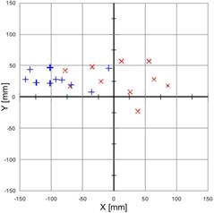
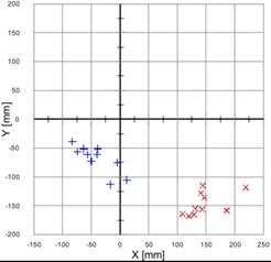
Fig. 4. Measurement with the controller P on, with the following settings: proportional term = 250 ('+' - turbine off, 'x' - turbine on): standard velocity at straight lines (on the left), increased velocity at straight lines (on the right)
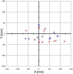
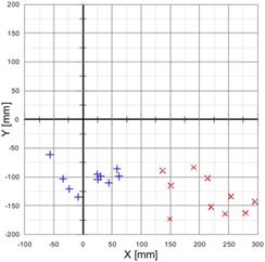
Fig. 5. Measurement with the controller PI on, with the following settings: proportional term = 150; integral term = 50; time constant = 1 ('+' - turbine off, 'x' - turbine on): standard velocity at straight lines (on the left), increased velocity at straight lines (on the right)
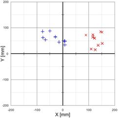
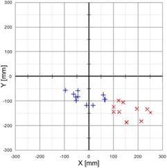
Fig. 6. Measurement with the controller PID on, with the following settings: proportional term = 150; integral term = 50; derivative term = 300; time constant = 1 ('+' - turbine off, 'x' - turbine on): standard velocity at straight lines (on the left), increased velocity at straight lines (on the right)
On the basis of the obtained results, the statistical analysis [20] has been carried out and the following values (put together in Tables 1) have been determined:
· arithmetic mean:
| (5) |
· value of the module of arithmetic mean:
| (6) |
· standard deviation:
| (7) |
· typical variable field, determining the interval of an appearance of the value:
| (8) |
· median.
Table 1
Statistical analysis for standard velocity and increased velocity at straight lines
|
|
Standard velocity |
Increased velocity at straight lines |
||||||
|
Controller type |
Controller P |
Controller P |
||||||
|
Turbine |
Off |
On |
Off |
On |
||||
|
Coordinate |
x |
y |
x |
y |
x |
y |
x |
y |
|
Arithmetic mean [mm] |
–89.1 |
29.2 |
7.8 |
27.7 |
–41.6 |
–68.5 |
146.9 |
–146.3 |
|
Module of arithmetic mean [mm] |
93.8 |
28.8 |
80.1 |
207.3 |
||||
|
Standard deviation [mm] |
40.2 |
12.1 |
53.8 |
23.5 |
28.9 |
22.6 |
30.9 |
19.1 |
|
Typical variable field [mm] |
–129.3 –48.9 |
17.1 41.3 |
–46.0 61.6 |
4.2 51.2 |
–70.5 –12.7 |
–91.1 –45.9 |
116.0 177.8 |
–165.4 –127.2 |
|
Median [mm] |
–97.5 |
27.5 |
19 |
26.5 |
–45.0 |
–61.0 |
142.0 |
–155.5 |
|
Controller type |
Controller PI |
Controller PI |
||||||
|
Turbine |
Off |
On |
Off |
On |
||||
|
Coordinate |
x |
y |
x |
y |
x |
y |
x |
y |
|
Arithmetic mean [mm] |
19.3 |
–6.2 |
28.1 |
–18.5 |
21.0 |
–107.5 |
213.3 |
–131.8 |
|
Module of arithmetic mean [mm] |
20.3 |
33.6 |
109.5 |
250.7 |
||||
|
Standard deviation [mm] |
45.2 |
18.4 |
50.7 |
25.0 |
31.2 |
14.1 |
48.3 |
29.6 |
|
Typical variable field [mm] |
–25.9 64.5 |
–24.6 12.2 |
–22.6 78.8 |
–43.5 6.5 |
–10.2 52.2 |
–121.6 –93.4 |
165.0 261.6 |
–161.4 –102.2 |
|
Median [mm] |
23.0 |
–15.0 |
20.0 |
–33.0 |
27.5 |
–103.5 |
217.0 |
–138.5 |
|
Controller type |
Controller PID |
Controller PID |
||||||
|
Turbine |
Off |
On |
Off |
On |
||||
|
Coordinate |
x |
y |
x |
y |
x |
y |
x |
y |
|
Arithmetic mean [mm] |
–36.1 |
62.0 |
126.1 |
54.3 |
–22.2 |
–85.5 |
163.8 |
–139.9 |
|
Module of arithmetic mean [mm] |
71.7 |
137.3 |
88.3 |
215.4 |
||||
|
Standard deviation [mm] |
34.4 |
18.7 |
19.2 |
24.6 |
50.9 |
20.5 |
51.1 |
26.0 |
|
Typical variable field [mm] |
–70.5 –1.7 |
43.3 80.7 |
106.9 145.3 |
29.7 78.9 |
–73.1 28.7 |
–106.0 –65.0 |
112.7 214.9 |
–165.9 –113.9 |
|
Median [mm] |
–39.5 |
58.0 |
132.5 |
62.0 |
–45.0 |
–83.5 |
146.0 |
–139.0 |
4. Conclusion
Using the results of the conducted experimental research, the following conclusions can be drawn:
· for the P controller and the race with the standard velocity: results are much more concentrated for the turbine off, however general accuracy is higher for the turbine on;
· for the P controller and the race with increased velocity: for the turbine off smaller error has been obtained at the end, but not much better repeatability of results, with respect to the system with the turbine on. Compared with the race with the standard velocity the error for X coordinate is over two times bigger. With the turbine on, the final error is about seven times higher, at a little higher repeatability;
· for the PI controller and the race with the standard velocity: measurement points are mixed with one another. Results for the turbine on characterize themselves with similar dispersion and arrangement as with the P controller, but results for the turbine off do have not much bigger dispersion, and the centre point of those measurements is located very close to the centre of the customary coordinate system;
· for the PI controller and the race with increased velocity: results are divided with respect to each other. For the race with the turbine off, dispersion of the results is close to the measurements taken with the P controller, however for the turbine on it is noticeably higher, and results are significantly divergent from the expected one, on average as many as 250 mm;
· for the PID controller and the race with the standard velocity: results for the turbine off and the turbine on are demarcated from each other, better accuracy has been obtained for the race with the turbine off;
· for the PID controller and the race with increased velocity: the distribution and measurement values are close to the measurements with the PI controller, however the module of the arithmetic average value is smaller;
· accuracy of positioning could be significantly enhanced by increasing the quantity of holes in encoder discs. Currently there are eighteen holes; a better solution would be increasing that amount to more than sixty.
Although major objectives have been achieved, there are still a lot of aspects that can be improved such as: control algorithm, controller settings and several elements of the robot construction (e.g. encoders). In addition, the presented solution can be fully applied into other types of objects, such as autonomous driving platforms [21] that work in production halls and have predetermined driving trajectories. However, in such a case, additional physical phenomena that may occur during vehicle movement, such as friction or slip, should be included in the control program.
The research presented in this paper proves that the results of tests in manual tuning of regulators match the results when using other methods of selecting the regulator parameters [4-7]. However, the manual tuning method is time-consuming and each time it would have to be done for other trajectories. If other methods of parameter selection are used, programs are written only once and allow for entering different trajectories, and the algorithm finds new values of the controllers themselves.
References
[1] Bolton, W. (2003). Mechatronics: Electronic control system in Mechanical and Electrical system. Prentice Hall.
[2] Ismail, A.H., Abdul Zaman, A.M., & Terashima, K. (2016). Fuzzy logic approach for line following mobile robot using an array of digital sensors. IJAIEM, 5(7), 108-115.
[3] Zhongsheng, H., & Yuanming, Z. (2013). Model based control and MFAC, which is better in simulation?. IFAC Proceedings Volumes, 46(13), 82-87.
[4] Dai, Y., & Lee, S.G. (2012). The leader-follower formation control of nonholonomic mobile robots. International Journal of Control, Automation and Systems, 10(2), 350-361.
[5] Maggio, M., Bonvini, M., & Leva, A. (2012). The PID+ p controller structure and its contextual autotuning. Journal of Process Control, 22(7), 1237-1245.
[6] Sun, L., Li, D., & Lee, K.Y. (2016). Optimal disturbance rejection for PI controller with constraints on relative delay margin. ISA Transactions, 63, 103-111.
[7] Zemliak, A. (2008). Frontiers in Robotics, Automation and Control. InTech.
[8] Gosim, N.W., Faisal, T., Al-Assadi, H.M.A.A., & Iwan, M. (2012). Pick and place ABB working with a liner follower robot. Procedia Engineering, 41, 1336-1342.
[9] Wochal, M., Wójcik, Ł., Zając, T., & Cekus D. (2012). The project of the Line-follower mobile robot. Proceedings of the V Interfaculty Seminar of Scientific Circles of Czestochowa University of Technology (Vol. I, pp. 123-127), (in Polish).
[10] Bueno, A.V., Velásquez, J.A., & Milanez, L.F. (2012). Internal combustion engine indicating measurements. Applied Measurement Systems. InTech. Available from: http://www.intechopen. com/books/applied-measurement-systems/internal-combustion-engine-indicating-measurements.
[11] Datta, A., Mukherjee, D., & Saha, H. (2014). A dsPIC based novel digital sinusoidal pulse-width modulation technique for voltage source inverter applications. Microprocessors and Microsystems, 38(7), 649-658.
[12] Peng, Z., Wen, G., Rahmani, A., & Yu, Y. (2013). Leader-follower formation control of nonholonomic mobile robots based on a bioinspired neurodynamic based approach. Robotics and Autonomous Systems, 61(9), 988-996.
[13] Borkowski, P. (2010). AVR i ARM7. Programowanie mikrokontrolerów dla każdego. Gliwice: Wydawnictwo Helion (in Polish).
[14] Murray, R.M. (2007). Recent research in cooperative control of multivehicle systems. Journal of Dynamic Systems, Measurement, and Control, 129(5), 571-583.
[15] Nartowicz, T. (2012). Design of Fractional Order Controller Satisfying Given Gain and Phase Margin for a Class of Unstable Plant with Delay. Acta Mechanica et Automatica, 6, 41-45.
[16] Léchevin, N., Rabbath, C.A., & Sicard, P. (2006). Trajectory tracking of leader-follower formations characterized by constant line-of-sight angles. Automatica, 42(12), 2131-2141.
[17] Roldão, V., Cunha, R., Cabecinhas, D., Silvestre, C., & Oliveira, P. (2014). A leader-following trajectory generator with application to quadrotor formation flight. Robotics and Autonomous Systems, 62(10), 1597-1609.
[18] Stania, M., Posiadała, B., & Stetter, R. (2010). Computer-aided design of mechatronic systems on the example of an autonomous transport vehicle. Transport Przemysłowy i Maszyny Robocze, 2(8), 86-92 (in Polish).
[19] Fax, J.A., & Murray, R.M. (2004). Information flow and cooperative control of vehicle formations. IEEE Transactions on Automatic Control, 49(9), 1465-1476.
[20] Özbilge, E. (2016). On-line expectation-based novelty detection for mobile robots. Robotics and Autonomous Systems, 81, 33-47.
[21] Vapnik, V.N. (1998). Statistical Learning Theory Hardcover. New York: John Wiley & Sons.