Analysis of the loads occurring in a modular hip joint endoprosthesis
Michał Sobociński
Journal of Applied Mathematics and Computational Mechanics |
 Download Full Text |
ANALYSIS OF THE LOADS OCCURRING IN A MODULAR HIP JOINT ENDOPROSTHESIS
Michał Sobociński
Institute of Mechanical Technology,
Czestochowa University of Technology
Częstochowa, Poland
sobocinski@iop.pcz.pl
Abstract. This paper contains the results of the load analysis of a modular hip joint endoprosthesis, performed by means of the finite elements method, using Autodesk Simulation Mechanical 2016 software. A geometric model was created based on real solutions using Autodesk Inventor Professional. The obtained results make it possible to indicate the “weak points” of the accepted solution, and thus counteract the subsequent effects resulting from premature wear of endoprosthesis elements.
Keywords: endoprosthesis, FEM, contact stress, strain
1. Introduction
The aim of this study was a numerical strength analysis with the use of the finite elements method, performed in a virtual hip joint for friction associations most often used in hip joint prosthesoplasty. Applying modular endoprostheses allows for an appropriate selection of friction pairs with respect to the specific biomechanical situation. In the case of solutions of this type, it is also possible to replace only the damaged or worn out friction elements of an endoprosthesis, which minimizes the extent of an eventual revision procedure. At the initial study stage, it is appropriate to apply analytic solutions aimed at indicating the areas where damages or premature wear of cooperating elements may occur.
2. Strength analysis
A mechanical system deforms under loads, and its particular points undergo linear and angular displacements. Knowledge of these displacements is necessary when the conditions of system rigidity are being tested.
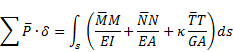
For the purpose of the determination of displacements, the principle of virtual work [1] can be applied, according to which the work of virtual loads on real displacements is equal to the work of virtual cross-sectional forces on real displacements:
|
|
where:
![]() - virtual load,
- virtual load,
![]() - real displacement
at the point of application of force
- real displacement
at the point of application of force ![]() ,
,
![]() - cross-sectional
forces relevant to a real load,
- cross-sectional
forces relevant to a real load,
![]() - bending rigidity of
a system,
- bending rigidity of
a system,
![]() - compression rigidity
of a system,
- compression rigidity
of a system,
![]() - shear rigidity of a
system,
- shear rigidity of a
system,
![]() - coefficient
dependent on the shape of a cross-section.
- coefficient
dependent on the shape of a cross-section.
Assuming that a generalized (linear or
angular) displacement ![]() is searched for at the
selected point of the system, when a virtual load in the form of a unit
generalized force
is searched for at the
selected point of the system, when a virtual load in the form of a unit
generalized force ![]() (force or moment,
depending on the sought-after displacement) with the direction of the
sought-after displacement is applied at this point, then
after substituting in the formula, we obtain:
(force or moment,
depending on the sought-after displacement) with the direction of the
sought-after displacement is applied at this point, then
after substituting in the formula, we obtain:
|
|
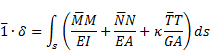
or
|
|
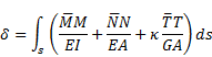
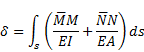
This equation presents the Maxwell-Mohr formula [2]. In the case of a construction where the ratio of the height of the cross-section to its length is as follows:
|
|
|
impact of lateral forces on the value of displacements is negligible, then the formula is simplified to the following form:
|
|
To determine stresses and displacements in endoprosthesis elements, the Huber- -Mises-Hencky hypothesis was assumed. The reduced stress value is described by the equation:
|
|
|
with the values of the stresses:
![]()
![]()
Applying the equation:
|
|
the equation (6) can get the form:
|
|
|
3. Numerical analysis of the loads affecting the modular hip joint endoprosthesis
The numerical analysis was performed based on the finite elements method using Autodesk Simulation Mechanical 2016 software.
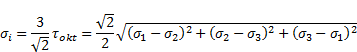
In the geometric model presented in Figure 1,
the dimensions of a real poly-
ethylene cup and head of the hip joint endoprosthesis ![]() 32 mm in diameter were
assumed. In the stem section, a part closer to the modular set based on widely
applied solutions [3] was used. The geometric model was built using Autodesk
Inventor Professional 2016 software. Due to the type of virtual fastening, the
geometric model of the cup did not have so-called “longitudinal cuts” that
counteract the rotation of the cup.
32 mm in diameter were
assumed. In the stem section, a part closer to the modular set based on widely
applied solutions [3] was used. The geometric model was built using Autodesk
Inventor Professional 2016 software. Due to the type of virtual fastening, the
geometric model of the cup did not have so-called “longitudinal cuts” that
counteract the rotation of the cup.
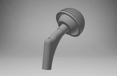
Fig. 1. Geometric model
The system of restraints and loads was based on the Będziński’s active model, modified and simplified for the purpose of the simulation. The values of loads were assumed on the basis of the literature data [4-7].
The following values were assumed:
P1 = 700 N - load resulting from a patient’s weight,
P2 = 50 N - loads resulting from the work of muscles.
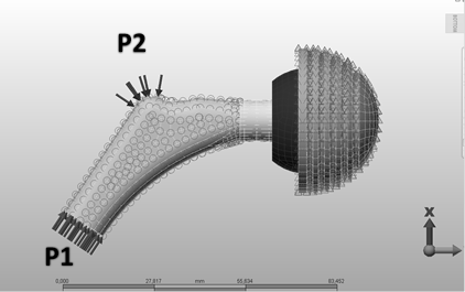
Fig. 2. Model of the loads affecting the analyzed system
In the tribological sphere of the system’s cooperation, contact with
a possibility of the movement of the head around the cup, with a friction
coefficient ![]() = 0.2, was
modeled; however, the presented static analysis does not include considerations
in this respect.
= 0.2, was
modeled; however, the presented static analysis does not include considerations
in this respect.
In the examples in question, the following material combinations were analyzed:
Table 1
Combination of biomaterials
|
Number of association |
Stem |
Head |
Cup |
|
1. |
Ti6Al4V |
Al2O3 |
UHMWPE |
|
2. |
Ti6Al4V |
CoCrMo |
UHMWPE |
|
3. |
Ti6Al4V |
Ti6Al4V |
UHMWPE |
The parameters of the materials assumed in the analysis:
Table 2
Mechanical features of biomaterials
|
Element of the model |
Young’s module [MPa] |
Poisson’s coefficient n |
|
Alloy CoCrMo |
2.0 × 10⁵ |
0.3 |
|
Alloy Ti6Al4V |
1.1 × 10⁵ |
0.3 |
|
UHMWPE |
1.0 × 10³ |
0.4 |
|
Ceramics Al2O3 |
3.8 × 10⁵ |
0.22 |
Figures 3-6 illustrate the example stress, strain and displacement distributions for the association: stem - Ti6Al4V, head - Al2O3, cup UHMWPE.
Fig. 3. Stress distribution for the association: stem - Ti6Al4V, head - Al2O3, cup UHMWPE
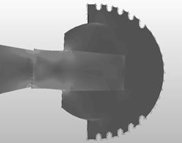
Fig. 4. Enlarged area including the maximum values of stresses for the association: stem - Ti6Al4V, head - Al2O3, cup UHMWPE
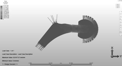
Fig. 5. Strain distribution for the association: stem - Ti6Al4V, head - Al2O3, cup UHMWPE
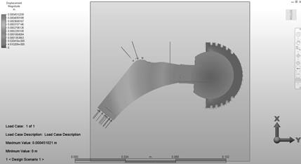
Fig. 6. Displacement distribution for the association: stem - Ti6Al4V, head - Al2O3, cup UHMWPE
Figure 7 illustrates a specification of the maximum stresses in the analyzed configurations. The highest values of stresses were obtained for the association: stem - Ti6Al4V, head - Al2O3, cup UHMWPE, with the maximum value at the level of 416 MPa. A lower value of stresses (408 MPa) was obtained for the association: stem - Ti6Al4V, head - CoCrMo, cup UHMWPE; while the lowest value (391 MPa) - for the configuration: stem - Ti6Al4V, head - Ti6Al4V, cup UHMWPE. The concentration of the stresses in all the cases was placed in the area of contact of the endoprosthesis stem with its head. It should be noted that it is a modular endoprosthesis, and therefore there is a contact between the tapered surface of the stem and the internal part of the opening in the head in this place.
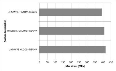
Fig. 7. Values of the maximum stresses with the analyzed associations
In all the analyzed cases, the highest values of strains occurred in the cup made of UHMWPE in the area of its contact with the endoprosthesis head. The maximum strains in all three cases of associations oscillated around 0.014 mm. The contact of the endoprosthesis hard head with a relatively flexible material of the cup could have caused such behavior of the cooperating parts. No displacement of the strains to the deeper parts of the cup has been recorded.
Due to the type of modeling of the adopted system, the proximal part of the endoprosthesis stem, where a load was applied, underwent the largest displacements. The values of the maximum displacements oscillated around 0.4 mm.
4. Conclusions
The highest stresses have been presented in the case of cooperation of the configuration: cup UHMWPE, head Al2O3, stem Ti6Al4V. In all the analyzed associations, one can notice that there has been a concentration of stresses in the area of contact between the tapered surface of the stem with the internal part of the opening in the endoprosthesis head. The highest values of the strains, which could have been foreseen, have been obtained in the area of contact between the endoprosthesis cup and head. The application of a polyethylene head allows for counteracting the transfer of stresses and strains to the deeper parts of the material, and thereby to the pelvic bone.
The conducted analysis allows for indicating the “weak points” of the adopted solution, and thereby counteracting the subsequent effects resulting from the premature wear of the endoprosthesis elements.
It is reasonable to carry out a further analysis of the suggested model and supplement it with additional elements, such as, e.g., contact with a bone.
References
[1] http://kmm.p.lodz.pl/dydaktyka/zb_zad/MB0300.pdf
[2] Gabryszewski Z., Teoria sprężystości i plastyczności, Oficyna Wydawnicza Politechniki Wrocławskiej, Wrocław 2001.
[3] http://www.medgal.com.pl/pl,ms-produkty-0-0-produkty.html
[4] Będziński R., Biomechanika inżynierska, Oficyna Wydawnicza Politechniki Wrocławskiej, Wrocław 1997.
[5] Madej T., Ryniewicz A., Modelowanie i symulacje wytrzymałościowe w stawie biodrowym zaopatrzonym protezą nakładkową jako procedura diagnostyczna przed zabiegiem kapoplastyki, Tribologia 2013, 2.
[6] Gierzyńska-Dolna M., Tribologia, Wydawnictwo Politechniki Częstochowskiej, Częstochowa 2002.
[7] Nabrdalik M., Stress occurring in the friction node of elements in the total knee endoprosthesis, Journal of Applied Mathematics and Computational Mechanics 2015, 14(2).