The influence of computational domain discretization on CFD results concerning aerodynamics of a vehicle
Marcin Sosnowski
Journal of Applied Mathematics and Computational Mechanics |
 Download Full Text |
 View in HTML format |
 Export citation |
@article{Sosnowski_2018,
   doi = {10.17512/jamcm.2018.1.08},
   url = {https://doi.org/10.17512/jamcm.2018.1.08},
   year = 2018,
   publisher = {The Publishing Office of Czestochowa University of Technology},
   volume = {17},
   number = {1},
   pages = {79--88},
   author = {Marcin Sosnowski},
   title = {The influence of computational domain discretization on CFD results concerning aerodynamics of a vehicle},
   journal = {Journal of Applied Mathematics and Computational Mechanics}
}
TY - JOUR DO - 10.17512/jamcm.2018.1.08 UR - https://doi.org/10.17512/jamcm.2018.1.08 TI - The influence of computational domain discretization on CFD results concerning aerodynamics of a vehicle T2 - Journal of Applied Mathematics and Computational Mechanics JA - J Appl Math Comput Mech AU - Sosnowski, Marcin PY - 2018 PB - The Publishing Office of Czestochowa University of Technology SP - 79 EP - 88 IS - 1 VL - 17 SN - 2299-9965 SN - 2353-0588 ER -
Sosnowski, M. (2018). The influence of computational domain discretization on CFD results concerning aerodynamics of a vehicle. Journal of Applied Mathematics and Computational Mechanics, 17(1), 79-88. doi:10.17512/jamcm.2018.1.08
Sosnowski, M., 2018. The influence of computational domain discretization on CFD results concerning aerodynamics of a vehicle. Journal of Applied Mathematics and Computational Mechanics, 17(1), pp.79-88. Available at: https://doi.org/10.17512/jamcm.2018.1.08
[1]M. Sosnowski, "The influence of computational domain discretization on CFD results concerning aerodynamics of a vehicle," Journal of Applied Mathematics and Computational Mechanics, vol. 17, no. 1, pp. 79-88, 2018.
Sosnowski, Marcin. "The influence of computational domain discretization on CFD results concerning aerodynamics of a vehicle." Journal of Applied Mathematics and Computational Mechanics 17.1 (2018): 79-88. CrossRef. Web.
1. Sosnowski M. The influence of computational domain discretization on CFD results concerning aerodynamics of a vehicle. Journal of Applied Mathematics and Computational Mechanics. The Publishing Office of Czestochowa University of Technology; 2018;17(1):79-88. Available from: https://doi.org/10.17512/jamcm.2018.1.08
Sosnowski, Marcin. "The influence of computational domain discretization on CFD results concerning aerodynamics of a vehicle." Journal of Applied Mathematics and Computational Mechanics 17, no. 1 (2018): 79-88. doi:10.17512/jamcm.2018.1.08
THE INFLUENCE OF COMPUTATIONAL DOMAIN DISCRETIZATION ON CFD RESULTS CONCERNING AERODYNAMICS OF A VEHICLE
Marcin Sosnowski
Jan Dlugosz University in Czestochowa
Czestochowa, Poland
m.sosnowski@ajd.czest.pl
Received: 22 February 2018;
Accepted: 10 March 2018
Abstract. The paper presents research concerning the influence of computational domain discretization on the results of CFD analysis. Tetrahedral and polyhedral numerical mesh types are analyzed and the mesh convergence index is calculated. The obtained results are compared to the experimental measurements concerning the estimation of drag coefficient of the vehicle model. The research carried out indicates the great influence of pre-process-ing on the reliability of the obtained results. Moreover, the advantages of polyhedral mesh over tetrahedral mesh are pointed out in the paper.
MSC 2010: 76G25, 76M25
Keywords: computational domain discretization, fluid dynamics, aerodynamics, AHMED body, drag coefficient
1. Introduction
Various mathematical methods have recently been applied to investigate several cases related to the contemporary science [1] and technology [2-4]. Computational Fluid Dynamics (CFD) is one of such methods and its application as a research tool is common in various industries including automotive [5] and [6], civil-engineering [7-11], power engineering [12, 13] and others [14]. CFD allows for low-cost product design and/or improvement. It applies numerical methods of solving nonlinear differential equations describing fluid flow, heat and mass transfer, chemical reactions (combustion) and others. Majority of the above mentioned equations do not have analytical solutions, therefore approximate numerical methods have to be applied to solve them. The level of approximation contributes to the reliability of the obtained results because the round-off errors and truncation errors influence the solution accuracy. The truncation errors can be minimized by improving the pre‑processing stage of CFD, which is the computational domain discretization (meshing). It highly contributes to the quality of obtained results as well as the numerical stability and convergence of the investigated case [15, 16].
The discretization of the computational domain can be achieved with the application of three different mesh types depicted in Figure 1: hexahedral (HEX), tetrahedral (TETRA) and polyhedral (POLY). All types of mesh elements are characterized by different numerical diffusion which directly influences the quality of the result: HEX elements are least diffusive while TETRA elements are most diffusive [16]. Unfortunately, the numerical diffusion of HEX mesh increases in the case of the flow that is not perpendicular to the cell faces. Moreover it is not always possible to build a HEX mesh for complex geometries. Therefore such a mesh type is not commonly applied in rapid prototyping. Despite the high numerical diffusion of TETRA mesh, the unquestionable advantage of this mesh type is the highly‑ -automated process of generation. On the other hand, TETRA cells cannot be stretched excessively, so a significantly larger number of elements has to be used in order to properly represent the investigated geometry.
|
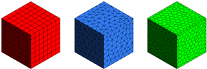
Fig. 1. Examples of numerical mesh types: hexahedral (a), tetrahedral (b) and polyhedral (c)
POLY elements are worth investigating as their numerical diffusion is at a level comparable to HEX and in addition, POLYs can easily by applied to describe even very complicated geometries [13]. The individual POLY element neighbors with more cells in comparison to HEX and TETRA, which improves the calculation of gradients and allows better heat and mass transfer through numerous faces. In consequence, the application of POLY mesh reduces the influence of numerical diffusion in case of the flow not perpendicular to any of the cell face. It is advantageous in situations where no prevailing flow direction can be identified and leads to more accurate solution achieved with a lower cell count [16]. POLY mesh generation is a simple conversion of TETRA mesh to POLY mesh by decomposition of cells into multiple sub-volumes.
The research performed concerns the application of the above-mentioned numerical methods to investigate the drag coefficient of a vehicle model. Research into aerodynamic parameters of a single vehicle as well as arrangement of subsequent vehicles driving in a so-called platoon are carried out in the automotive industry in order to reduce the fuel consumption and in consequence increase the efficiency of the analyzed design [17]. Therefore research dedicated to the estimation of the influence of computational domain discretization on CFD results concerning the aerodynamics of a vehicle are purposeful.
2. Methods
2.1. The numerical setup
The research object is a vehicle model described in [17] and commonly called the AHMED body. It is one of the most popular models used as a simplified vehicle shape to predict the fundamental flow physics associated with a vehicle wake. The dimension of the analyzed body used in the research is 261×97.25×72 mm (L×W×H) and the frontal area is 7e-3 m2. The slant angle of the rear of the vehicle is set to 25 degrees.
The simulations were performed using ANSYS Fluent 18.1. The identical computational models (except for the mesh) were used for all analyzed cases. The size of the computation domain corresponds to the experimental test stand. The distance of the inlet plane to the vehicle model was set to 0.5 m.
The bottom surface of the AHMED body was located at 0.02 m above the ground. The solver was configured as pressure based, and the analysis were performed for a steady state. The 3D steady RANS equations were solved with the standard k–ε model. The choice of the standard k–ε model was made based on a previous extensive validation study for the aerodynamics of vehicles [17].
Pressure-velocity coupling was taken care of by the SIMPLEC algorithm based on the relation between velocity and pressure to enforce mass conservation and to obtain the pressure field. Pressure interpolation was second-order, and second-order discretization schemes were used for both the convection terms and the viscous terms of the governing equations. Convergence was monitored carefully and the iterations were terminated when all residuals showed no further reduction up to a certain threshold with an increasing number of iterations.
Air at normal conditions was the fluid medium. The velocity-inlet boundary condition type was assigned to the inlet with velocity magnitude normal to the boundary equal 8 m/s (corresponding to carried out experiment). The outlet of the computational domain was defined as pressure-outlet with ambient static pressure. A wall with no slip shear condition and no roughness was assigned to the remaining surfaces (car model and wind tunnel walls).
2.2. Computational domain discretization
The meshing process was performed using ANSYS Meshing 18.1. TETRA and POLY elements were used to discretize the computational domain. Figure 2 shows part of the mesh distribution on the surface of the AHMED body for both mesh types and each of the three analyzed mesh densities.
The size function was set to UNIFORM in order to obtain the most regular mesh. Moreover the maximal face size as well as maximal cell size constrains were set to the value corresponding to 1/20 of the computational domain length. Additional face sizing on surfaces representing car models was altered in order to obtain different mesh resolutions. The growth rate equal to 1.1 was set in order to refine the mesh in the vicinity of the analyzed vehicle model. Such a meshing procedure was previously applied and validated in [17-18].
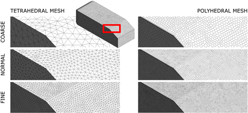
Fig. 2. Analyzed cases of computational domain discretization
The experimental research described in [17] was carried out in order to validate the obtained numerical results in an open-circuit wind tunnel facility of cross-section equal 1 m2. The inlet velocity of air in the wind tunnel was 8 m/s resulting in the Reynolds number of 1,4e+5, based on the length of the analyzed body. Air pressure and temperature were measured continuously during wind tunnel operation. The vehicle model was made of wood and it was aligned with the direction of the wind in the tunnel. The load on the body was measured with an aerodynamic balance, which was located under the tunnel floor and was attached to the body through a holder.
The investigated drag coefficient was calculated on the basis of equation (1):
|
|
|
where:
Fd - measured drag force in the direction of the flow,
r - air density,
u - flow velocity,
A - reference area.
2.3. Mesh dependency analysis
The mesh dependency analysis applied within the carried out research to estimate the discretization error is based on Richardson Extrapolation [19]. The representative mesh size h was defined according to equation (2) based on [16, 19].
|
|

where:
DVi - volume of the ith mesh element,
N - total number of mesh elements.
The mesh refinement factor r was calculated as quotient of representative size of coarse and fine mesh (3):
|
|
|
with assumption: ![]() .
.
The order of convergence p was calculated based on equation (4) where e32 = f3 – f2 and e21 = f2 – f1. It was solved using fixed-point iteration with the initial guess equal to the first term:
|
|
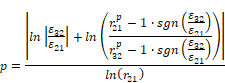
fk denotes the value of the variable important to the objective of the simulation study for a solution obtained with the kth mesh. The drag coefficient was chosen as the most representative variable within the confines of the research. The extrapolated values were calculated on the basis of equation (5), approximate relative error on the basis of eq. (6), extrapolated relative error on the basis of eq. (7) and mesh convergence index C on the basis of eq. (8) based on [16, 19]:
|
|
|
||||
|
|
|
||||
|
|
|
||||
|
|
|
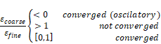
The mesh convergence is evaluated using formula (9):
|
|
3. Results
The applied meshing settings resulted in the final mesh consisting of approx. 230 to 1500 thousand elements depending on the desired mesh resolution as stated in Table 1. The mesh quality was also taken into consideration. The quality analysis provided a metric that ranges between 0 and 1. A value of 1 indicates a perfect element while a value of 0 indicates that the element has a zero or negative volume. The element of the worst quality generated throughout the entire research was characterized by the quality index of 0.154 for TETRA mesh and 0.207 for POLY mesh (details in Table 1). Therefore it was assumed that the mesh did not affect the numerical stability of the computational model.
Table 1
Analyzed cases and results
|
|
TETRAHEDRAL MESH |
POLYHEDRAL MESH |
||||
|
Coarse |
Normal |
Fine |
Coarse |
Normal |
Fine |
|
|
Number of mesh elements |
232 820 |
607 190 |
1 547 250 |
231 325 |
610 087 |
1 501 668 |
|
Mesh element of worst quality |
0.154 |
0.165 |
0.156 |
0.287 |
0.207 |
0.268 |
|
Mesh convergence index |
– |
5.13% |
1.60% |
– |
0.02% |
0.37% |
|
Mesh convergence |
not converged |
converged |
||||
|
Iterations to model convergence |
unstable |
327 |
351 |
355 |
297 |
277 |
The mesh convergence index was higher for TETRA mesh in comparison to POLY mesh and the TETRA mesh was not converged. Moreover the number of solver iterations necessary to obtain the converged solution was lower for POLY mesh and in case of the coarsest TETRA mesh, the solution did not converge at all - the model was numerically unstable.
The wall shear on the surface of the analyzed AHMED body for both analyzed mesh types and three mesh resolutions is presented in Figure 2 in order to depict the influence of computational domain discretization on CFD results concerning aerodynamics of a vehicle. Moreover velocity (Figs. 3 and 4) as well as turbulence kinetic energy (Fig. 5) in the center‑plane of the domain are depicted.
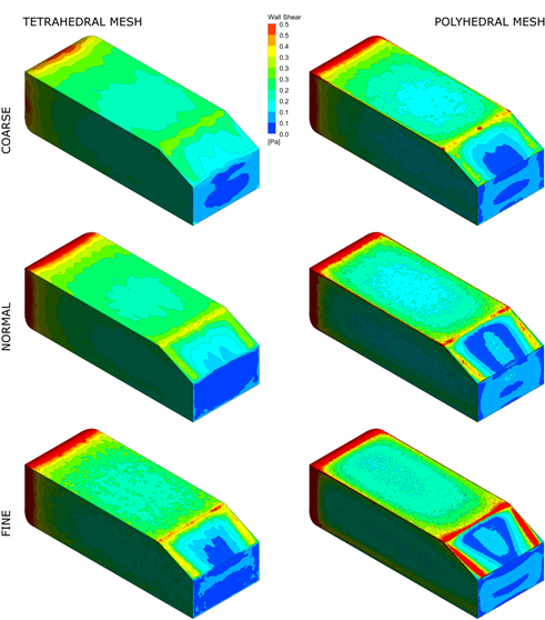
Fig. 2. Wall Shear on AHMED body surface for all analyzed cases
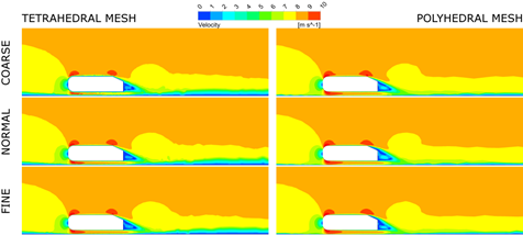
Fig. 3. Velocity magnitude in the center-plane of the domain
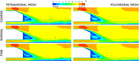
Fig. 4. Velocity magnitude in the center-plane of the domain (zoomed view)
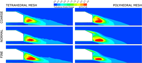
Fig. 5. Turbulence kinetic energy in the center-plane of the domain (zoomed view)
The drag coefficient obtained by CFD performed with TETRA and POLY meshes of different resolutions is normalized with the drag coefficient calculated on the basis of experimental research are depicted in Figure 6.
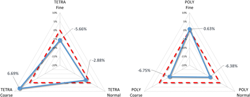
Fig. 6. Normalized drag coefficient obtained for different meshes in relation to the measured drag coefficient marked with red dotted line
4. Conclusions
The mesh quality estimated on the basis of the quality of the worst element is better for POLY mesh (0.207) than for TETRA mesh (0.154).
The number of iterations necessary to obtain the convergence of the model is lower for POLY mesh and the convergence for the coarse TETRA mesh could not be achieved due to the unstable behavior of the solution.
The qualitative results (Figs. 2-5) indicate the great influence of both the mesh type as well as the mesh resolution on the obtained results. Moreover, mesh artefacts can be observed for all analyzed TETRA meshes while POLY mesh seems to be free from such issues.
The quantitative comparison of CFD and experimental results in terms of drag coefficient indicates good agreement - the maximal error of 6.69 and –6.75% was obtained for coarse TETRA and POLY mesh respectively (Fig. 6). Moreover, the results obtained for TETRA mesh prove the lack of mesh convergence as the relative error varies from 6.69% (coarse) to –5.66% (fine) and the best agreement (–2.88%) is obtained for the normal mesh. In contrast, the quantitative results obtained for POLY mesh indicate mesh convergence as the lowest error (0.63%) is obtained for the fine mesh and the highest error (–6.75%) is obtained for the coarse mesh.
Therefore the main conclusion based on the carried out research is that the pre-processing stage of CFD analysis is crucial in terms of the reliability of the results and the mesh convergence studies have to be obligatorily performed in order to define the appropriate mesh resolution. Moreover the application of POLY mesh is vital for both the stability of the model as well as the number of iterations necessary to obtain the converged solution.
References
[1] Krzywanski, J., Grabowska, K., Herman, F., Pyrka, P., Sosnowski, M., Prauzner T., & Nowak, W. (2017). Optimization of a three-bed adsorption chiller by genetic algorithms and neural networks. Energy Conversion and Management, 153, 313-322.
[2] Mazal, J., Stodola, P., Prochazka, D., Kutej, L., Scurek, R., & Prochazka, J. (2016). Modelling of the UAV Safety Manoeuvre for the Air Insertion Operations. in International Workshop on Modelling and Simulation for Autonomous Systems, 337-346.
[3] Sztekler, K., Kalawa, W., Nowak, W., Stefanski, S., Krzywanski, J., & Grabowska, K. (2017). Using the adsorption chillers for utilisation of waste heat from rotary kilns. International Conference on Experimental Fluid Mechanics (EFM), Mikulov, Czech Republic, 650-653.
[4] Sztekler, K., Kalawa, W., Nowak, W., Stefanski, S., Krzywanski, J., & Grabowska, K. (2017). Using the adsorption chillers for waste heat utilisation from the CCS installation. International Conference on Experimental Fluid Mechanics (EFM), Mikulov, Czech Republic, 654-657.
[5] Jamrozik, A., Tutak, W., Kociszewski, A., & Sosnowski, M. (2013). Numerical simulation of two-stage combustion in SI engine with prechamber. Applied Mathematical Modelling, 37, 5, 2961-2982.
[6] Jamrozik, A., Tutak, W., Gnatowski, A., Gnatowska, R., Winczek, J., & Sosnowski, M. (2017). Modeling of thermal cycle CI engine with multi-stage fuel injection. Advances in Science and Technology. Research Journal, 11, 3, 179-186.
[7] Gnatowska, R. (2015). A study of downwash effects on flow and dispersion processes around buildings in tandem arrangement. Polish Journal of Environmental Studies, 24(4), 1571-1577.
[8] Gnatowska, R. (2008). Synchronization phenomena in systems of bluff-bodies. International Journal of Turbo and Jet Engines, 25, 2, 121-128.
[9] Gnatowska, R. (2011). Aerodynamic characteristics of three-dimensional surface-mounted objects in tandem arrangement. International Journal of Turbo and Jet Engines, 28, 1, 21-29.
[10] Moryn-Kucharczyk, E., & Gnatowska, R. (2007). Pollutant dispersion in flow around bluff-bodies arrangement. in Wind Energy, Springer, 49-53.
[11] Gnatowska, R. (2008). Aerodynamic characteristics of two-dimensional sharp-edged objects in tandem arrangement. Archives of Mechanics, 60, 6, 475-490.
[12] Krzywanski, J., Szyc, M., Nowak, W., & Kolenda, Z. (2016). Experience in modelling of a single-stage silica gel-water adsorption chiller. Technical Sciences/University of Warmia and Mazury in Olsztyn.
[13] Sosnowski, M., Krzywanski, J., & Gnatowska, R. (2017). Polyhedral meshing as an innovative approach to computational domain discretization of a cyclone in a fluidized bed CLC unit. in Energy and Fuels, 14, Suwala, W., Dudek, M., Leszczynski, J., & Lopata, S., Eds.
[14] Sosnowski, M. (2017). Computer aided optimization of a nozzle in around-the-pump fire suppression foam proportioning system. Engineering Mechanics 2017, 914-917.
[15] Sosnowski, M. (2017). Computational domain discretization in numerical analysis of flow within granular materials. International Conference on Experimental Fluid Mechanics (EFM), Mikulov, Czech Republic, 582-588.
[16] Sosnowski, M., Krzywanski, J., Grabowska, K., & Gnatowska, R. (2017). Polyhedral meshing in numerical analysis of conjugate heat transfer. International Conference on Experimental Fluid Mechanics (EFM), Mikulov, Czech Republic, 589-594.
[17] Gnatowska, R., & Sosnowski, M. (2017).The influence of distance between vehicles in platoon on aerodynamic parameters. International Conference on Experimental Fluid Mechanics (EFM), Mikulov, Czech Republic, 194-198.
[18] Gnatowska, R., Sosnowski, M., & Uruba, V. (2017). CFD modelling and PIV experimental validation of flow fields in urban environments. in Energy and Fuels, 14, Suwala, W., Dudek, M., Leszczynski, J., & Lopata, S., Eds.
[19] Celik, I.B., Ghia, U., Roache, P.J., & others (2008). Procedure for estimation and reporting of uncertainty due to discretization in CFD applications. Journal of Fluids Engineering-Transac- tions of the ASME, 130, 7.