Numerical simulations of structural behavior of sandwich panels subjected to concentrated static loads
Jolanta Pozorska
,Zbigniew Pozorski
,Łukasz Janik
Journal of Applied Mathematics and Computational Mechanics |
 Download Full Text |
 View in HTML format |
 Export citation |
@article{Pozorska_2017,
   doi = {10.17512/jamcm.2017.2.09},
   url = {https://doi.org/10.17512/jamcm.2017.2.09},
   year = 2017,
   publisher = {The Publishing Office of Czestochowa University of Technology},
   volume = {16},
   number = {2},
   pages = {113--121},
   author = {Jolanta Pozorska and  Zbigniew Pozorski and  Łukasz Janik},
   title = {Numerical simulations of structural behavior of sandwich panels subjected to concentrated static loads},
   journal = {Journal of Applied Mathematics and Computational Mechanics}
}
TY - JOUR DO - 10.17512/jamcm.2017.2.09 UR - https://doi.org/10.17512/jamcm.2017.2.09 TI - Numerical simulations of structural behavior of sandwich panels subjected to concentrated static loads T2 - Journal of Applied Mathematics and Computational Mechanics JA - J Appl Math Comput Mech AU - Pozorska, Jolanta AU - Pozorski, Zbigniew AU - Janik, Łukasz PY - 2017 PB - The Publishing Office of Czestochowa University of Technology SP - 113 EP - 121 IS - 2 VL - 16 SN - 2299-9965 SN - 2353-0588 ER -
Pozorska, J., Pozorski, Z., & Janik, �. (2017). Numerical simulations of structural behavior of sandwich panels subjected to concentrated static loads. Journal of Applied Mathematics and Computational Mechanics, 16(2), 113-121. doi:10.17512/jamcm.2017.2.09
Pozorska, J., Pozorski, Z. & Janik, �., 2017. Numerical simulations of structural behavior of sandwich panels subjected to concentrated static loads. Journal of Applied Mathematics and Computational Mechanics, 16(2), pp.113-121. Available at: https://doi.org/10.17512/jamcm.2017.2.09
[1]J. Pozorska, Z. Pozorski and �. Janik, "Numerical simulations of structural behavior of sandwich panels subjected to concentrated static loads," Journal of Applied Mathematics and Computational Mechanics, vol. 16, no. 2, pp. 113-121, 2017.
Pozorska, Jolanta, Zbigniew Pozorski, and Łukasz Janik. "Numerical simulations of structural behavior of sandwich panels subjected to concentrated static loads." Journal of Applied Mathematics and Computational Mechanics 16.2 (2017): 113-121. CrossRef. Web.
1. Pozorska J, Pozorski Z, Janik �. Numerical simulations of structural behavior of sandwich panels subjected to concentrated static loads. Journal of Applied Mathematics and Computational Mechanics. The Publishing Office of Czestochowa University of Technology; 2017;16(2):113-121. Available from: https://doi.org/10.17512/jamcm.2017.2.09
Pozorska, Jolanta, Zbigniew Pozorski, and Łukasz Janik. "Numerical simulations of structural behavior of sandwich panels subjected to concentrated static loads." Journal of Applied Mathematics and Computational Mechanics 16, no. 2 (2017): 113-121. doi:10.17512/jamcm.2017.2.09
NUMERICAL SIMULATIONS OF STRUCTURAL BEHAVIOR OF SANDWICH PANELS SUBJECTED TO CONCENTRATED STATIC LOADS
Jolanta Pozorska1, Zbigniew Pozorski2, Łukasz Janik2
1Institute of Mathematics, Czestochowa University of
Technology, Częstochowa, Poland
2Institute of Structural Engineering, Poznan University
of Technology, Poznań, Poland
jolanta.pozorska@im.pcz.pl, zbigniew.pozorski@put.poznan.pl
Received: 8 March 2017; accepted: 26 May 2017
Abstract. The paper presents numerical simulations of the behavior of sandwich panels loaded by static concentrated force. Two model classes (2D and 3D) are considered, and the results are compared with the effective width method. The comparison mainly concerns the displacements and stresses in the facings. The obtained results indicate the areas of conformity between the models but also show significant differences between them. The observed local effects are discussed and the surprising location of extreme stress in the facings is demonstrated.
MSC 2010: 65C20, 68U07, 68U20, 70C20, 74K20
Keywords: sandwich panels, concentrated loads, numerical simulations, local effects, the effective width method
1. Introduction
The subject of the paper are sandwich panels used in civil engineering. These are typical wall or roof panels consisting of two thin steel facings and a thick but flexible core. Such structures have excellent thermal insulation and a very good load-to-weight ratio. Not surprisingly, the sandwich panels are commonly used.
In recent times, more and more attention is paid to the issue of the influence of the concentrated loads on the structural behavior of sandwich panels. The interest in this problem is related to the excitations from equipment or installations that are encountered in engineering practice. Solar collectors, photovoltaic panels, work platforms and advertising panels are more often mounted directly to the sandwich panels. Therefore, there is a need to determine forces, stresses and displacements from these actions. At first glance, the issue may seem simple, but the complexity of the sandwich structure and the variety of boundary conditions make the problem interesting from a scientific point of view. It is worth noting that to date, the most common approach to the problem of analysis of layered panels subjected to concentrated loads was the execution of full-scale experimental tests. The examination of the composite sandwich panels made of glass fibre reinforced polymer facings and a modified phenolic core was presented in [1]. The experiments carried out on foam core sandwich beams with carbon/epoxy facings were discussed in [2]. The results of classical sandwich panel testing used in civil engineering were presented in [3].
One of the features of layered structures is the variety of mechanisms of failure [4]. In the case of concentrated forces, local effects resulting from high core susceptibility are important (bending and indentation). These phenomena were investigated in [5, 6]. Similar phenomena occur at the supports, although due to the much larger area of the support, they are not so intense [7]. To better understand the behavior of layered structures and the cause of failure initiation, numerical analyses are performed. The analyses of the GFRP sandwich floor under point load were presented in [8]. The solutions obtained using the finite element method (FEM) were compared with real experiments. In [9] another tool was used, namely the Generalized Differential Quadrature, to investigate shell structures under point loads. Numerical analyses have also shown the high sensitivity of sandwich panels to the variation of boundary conditions [10-12].
Experimental research is costly and time consuming, and numerical simulations require advanced software. Therefore, a much simpler method allowing for a fast and efficient (but less accurate) assessment of the structure condition are developed in parallel. In the case of sandwich panels subjected to concentrated loads, the effective width method is used that consists in replacing the plate with a beam of the appropriate width. This method was thoroughly analyzed in [13] and was included in the design recommendations [14].
The purpose of this paper is to compare two classes of numerical models (2D and 3D) in the context of the problem of the influence of concentrated forces on layered systems. The issues of stress concentration and localization of extreme deformations will be discussed. Solutions obtained using the finite element method will be compared to results received using the effective width method (EWM).
2. Description of the problem and the research program
A single-span plate of length L, width B and the total depth D is considered (Fig. 1). The plate is subjected to concentrated load F, which is perpendicular to the surface of the plate. The force is located at a point with (x, y) coordinates. The system is simply supported at the two opposite edges. The right support has the ability to move horizontally. Such a static scheme, though simple, is very common in practice. It is more important, however, that the phenomena observed in a simple static scheme are easier to assess and interpret.
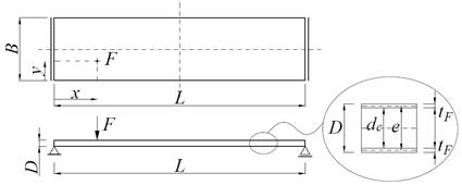
Fig 1. Geometry and support conditions of the sandwich panel
In this paper, we consider a plate with flat facings that are made of steel. The facings (upper and lower) have a thickness tF = 0.5 mm. For the steel, an isotropic, perfectly elastic model of material was assumed, for which the modulus of elasticity EF = 210 GPa and Poisson ratio νF = 0.3. The core of the sandwich panel is made of polyurethane foam defined as homogeneous and isotropic material. Typical material parameters of polyurethane foam were specified, namely EC = 8.16 MPa and νC = 0.02, which corresponds to GC = 4 MPa.
To compare the different classes of models and identify the most important phenomena, 81 different static systems (for each model) were analyzed. Each of the systems had a different span L (2, 4 and 6 m), total depth of the panel D (80, 120, 180 mm) or load position (x, y). The following load positions were considered: (L/10, 0), (L/10, B/5), (L/10, B/2), (L/4, 0), (L/4, B/5), (L/4, B/2), (L/2, 0), (L/2, B/5) and (L/2, B/2). The width of the panels was constant B = 1 m, and the load value F = 1 kN. For each of the analyzed cases, focus was placed on the comparison of displacements and normal stresses in facings (acting on x and y directions), but stresses in the core were also observed. The solutions obtained for numerical models (2D and 3D) were compared with the results obtained using the effective width method. Details of this method can be found in [14].
3. Numerical models
3.1. 2D model
All numerical models have been prepared in the Abaqus system. The 2D model was created applying three-layered shell elements. Thickness, number of integration points and material parameters of each layer were specified respectively. For example, a sandwich with total depth D = 80 mm has the lower steel facing with the thickness of 0.5 mm, the polyurethane core with the thickness of 79.0 mm and the upper steel facing with the thickness of 0.5 mm (the material parameters were presented above). The model was discretized using four-node, general-purpose, finite membrane strains, conventional shell S4R elements with reduced integration and hourglass control. The mesh size was constant and equal to 0.02 m. The shell’s midsurface was defined as the reference surface containing the element's nodes. The support conditions and the load conditions were specified for the nodes of the model. The concentrated load F = 1 kN was applied in a single node. The load value corresponds to the level of real load capacity of a typical sandwich panel.
3.2. 3D model
The 3D model consists of three layers: two facings and a core. The facings were modeled using four-node, general-purpose, finite membrane strains, conventional shell S4 elements. The core of the panel was modeled using eight node linear brick C3D8 elements. A constant mesh size equal to 0.02 m was assumed throughout the whole model. Due to the model class, appropriate boundary conditions were defined. The panel was placed on two supports 0.10 m wide and B = 1 m long (like the panel). Because of the specific width of the supports, the overall length of the panel was 0.10 m greater than the span. The supports were modeled using R3D4 elements (rigid, three-dimensional, four node), and the support conditions were defined by the reference point. Interaction between the supports and the lower facing was assumed as a TIE type, which makes equal displacements of nodes. The load was applied to the upper facing. It was defined as a uniform pressure q = 625 kPa spread over 4 finite elements of the upper facing (0.04 × 0.04 m). This is the pressure that corresponds to the force of the value F = 1 kN. The form of the loading is adequate to the class of the model. The load was not defined as concentrated in a single node because this leads to unrealistic stresses and deformations.
4. Discussion of the results
4.1. Loading in the center of the panel
In the case of the force applied in the center of the sandwich panel, the extreme vertical displacements (displacements under the force) for 2D and 3D models are comparable (Table 1). The highest difference in displacements (about 43.5%) is obtained for short and thick panel (L = 2 m, D = 0.08 m), but for model L4D18 (L = 4 m, D = 0.18 m) the difference is 18.5%. Larger displacements are achieved (locally, under the force) in the 2D model. In the case of the 3D model, the force is distributed more evenly, resulting in a more even deflection of the whole panel. It is worth pointing out that the results shown in Table 1 for the 3D model correspond to the displacements on the lower facings. Extreme displacement of the upper facing is greater than of the lower one, and exceeds the extreme values obtained for the 2D model.
In the simplified method, the effective width was determined as if the panel was only subjected to bending. As a result, using this method, displacements obtained for larger spans are slightly higher than they are for numerical models, but for short and thin panels the displacements are heavily underestimated. This is obvious considering that just for short and thin panels, the shear deformations are very important.
Table 1
The comparison of extreme displacements w [m] for different geometry of sandwich panels, in the case of force applied in the center of the panel
|
Span L [m] |
2.0 |
4.0 |
6.0 |
||||||
|
Total depth D [m] |
0.08 |
0.12 |
0.18 |
0.08 |
0.12 |
0.18 |
0.08 |
0.12 |
0.18 |
|
Extreme displacement w [mm] (model 2D) |
3.52 |
2.24 |
1.45 |
8.56 |
4.82 |
2.82 |
19.6 |
10.1 |
5.37 |
|
Extreme displacement w [mm] (model 3D, lower facing) |
2.77 |
1.65 |
1.01 |
7.82 |
4.23 |
2.38 |
18.8 |
9.48 |
4.94 |
|
Extreme displacement w [mm] (the effective width method) |
1.75 |
1.47 |
1.34 |
6.51 |
4.27 |
3.28 |
17.3 |
9.73 |
6.39 |
In the lower facing, in the direction consistent with the span, there are tensile normal stresses. Good compatibility of these stress values was obtained for all models except the vicinity of the point of force application (see Fig. 3). At this point, the stresses are highest in the 3D model. For the panel, span L = 4 m and depth D = 0.08 m, the difference between the extreme stress in 2D and 3D model is about 49%, but for the short and thin plate (L = 2 m, D = 0.08 m) the difference reaches up to 89%. The effective width method (EWM) gives results similar to the numerical solution of the 2D model.
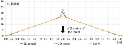
Fig 2. Normal stress sxx in the lower facing of sandwich panel (L = 4 m, D = 0.12 m) for y = 0.5 m
In the case of the upper facing that is mainly compressed, the situation is very similar to that of the lower facing but even more emphasized. The only difference is that the worst compatibility is achieved with thick panels. Over the entire area, normal stresses are consistent between models, but at the point of load application, the 3D model exhibits strong deformation of the core. As a result, in the vicinity of applied force, the facing has very high compressive stresses and even greater tensile stresses (several times greater than in the case of the 2D model). It is interesting that these local concentrations occur despite the distribution of the applied load in a certain area. Deformation of the facing at the place of load application explains the cause of such stress distribution (Fig. 3). The issue of stress concentrations in the vicinity of the load is one of the most important, which should be verified in a real experiment.
|
|
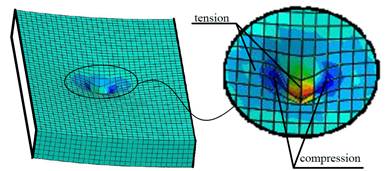
Fig 3. Deformation of the upper facing at the place of load application
4.2. Loading at the edge of the panel
In the case of the force applied at the edge of the panel (x, y) = (L/2, 0), the extreme vertical displacements occur at the point of force application. The results are comparable for different models, however, in the case of thick and short panels, the difference reaches 45%, (see Table 2). For the model L6D18 (L = 6 m, D = 0.18 m) the difference in displacements is 14%. The results obtained using the effective width method are lower, especially in the case of small depth of the panel, because the method does not take torsion effects into account.
Table 2
The comparison of extreme displacements w [m] for different geometry of sandwich panels, in the case of force applied at the edge of the panel
|
Span L [m] |
2.0 |
4.0 |
6.0 |
||||||
|
Total depth D [m] |
0.08 |
0.12 |
0.18 |
0.08 |
0.12 |
0.18 |
0.08 |
0.12 |
0.18 |
|
Extreme displacement w [mm] (model 2D) |
7.35 |
4.70 |
3.05 |
13.7 |
8.00 |
4.82 |
26.3 |
14.1 |
7.92 |
|
Extreme displacement w [mm] (model 3D, lower facing) |
5.57 |
3.37 |
2.10 |
11.9 |
6.66 |
3.87 |
24.4 |
12.8 |
6.94 |
|
Extreme displacement w [mm] (the effective width method) |
3.49 |
2.93 |
2.68 |
6.51 |
4.27 |
3.28 |
17.3 |
9.73 |
6.39 |
The relationships observed for normal stresses (acting along the longitudinal direction) are quite clear. The thicker the plate, the better the compatibility of numerical models. In the 3D model, locally (i.e. under the applied force) we obtain higher stresses than in the 2D model. For panels with a thickness D = 0.18 m, this effect is not noticeable. The only doubts arise in the case of the 3D model of thin panels because of (locally) high values of normal tension stresses (Fig. 4). The stress results obtained using the effective width method (EWM) appear safe (cf. Fig. 4), although they differ considerably from numerical results. This is obvious because the simple beam model used in the EWM omits such effects as: spatial behavior of the plate, torsion or the core compression.
|
|
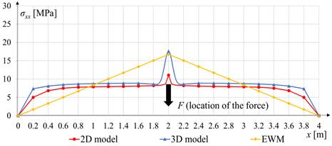
Fig 4. Normal stress sxx in the lower facing of sandwich panel (L = 4 m, D = 0.12 m) for y = 0.0 m
The results of normal stresses in the upper facing are very similar to those obtained for the force located in the center of the plate. The slight difference is that, due to the position of the load at the edge, local effects (for normal and shear stresses) are even more evident. On most of the facing area, compatibility between numerical models is good.
4.3. Localization of extreme normal stresses
During the analysis of normal stress distributions in the facings, an interesting phenomenon was observed in the case of a force located at one of the edges (x, y) = (L/2, 0). It is clearly visible on the lower facing, as there are no strong local deformations. It turns out that very often, in this facing, extreme longitudinal normal stresses occur not under applied force but on the opposite edge of the panel. This effect was not achieved only in the model L2D08 (L = 2 m, D = 0.08 m). The thicker the plate, the more visible this effect. The extreme stresses are best seen for the span L = 4 m (Fig. 5). This is slightly less noticeable for L = 6 m, and the least for L = 2 m. It should be emphasized that additional analyses show that the observed effect does not occur in plates of uniform structure (made of one material).
|
|
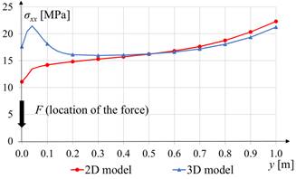
Fig. 5. The normal stresses sxx in the midspan of the lower facing (x = L/2) in the case of the panel L4D12 (L = 4 m, D = 0.12 m) and the load applied at the edge (x, y) = (L/2, 0)
5. Conclusions
Results of numerical analyses of laminated panels loaded with concentrated force were presented in the paper. Two numerical models (2D and 3D) were considered, and the results were compared with the engineering method of effective width. Displacement and stresses were determined for 2 classes of numerical models, 9 different force positions, 3 different spans and 3 different panel depths, meaning that 162 jobs were solved. Based on the results of the analyses, it can be stated that the considered 2D and 3D models are consistent with each other. The exception is the surroundings of the area where the force was applied. The 3D model considers the effect of core crushing, and as a result, local stress concentrations occur at the point of application of the load. Of course, they are most evident on the upper facing where we can locally observe both high compression and tension. The obtained local stress level should be verified experimentally, although it is expected that the 3D model is much closer to reality than the 2D model. The engineering method based on the so-called effective width in many cases was consistent with numerical solutions. Significant differences (usually underestimation) occurred in determining the displacements for short plates or when the load was applied near the edge. The latter case is obvious because the effective width method does not consider torsion. The effective width method usually provided safe stress values in facings. It was also observed in the analysis of normal stress distribution that when the force was applied at or near the edge of the plate, very high stresses appeared not under the force but on the opposite longitudinal edge. In the case of the lower facing and the 2D model, the values of these stresses were almost always higher than the stresses under the force. The presented results inspire further intensive research into the behavior of sandwich panels subjected to concentrated loads.
References
[1] Islam M.D., Aravinthan T., Behaviour of structural fibre composite sandwich panels under point load and uniformly distributed load, Composite Structures 2010, 93(1), 206-215.
[2] Kim J., Swanson S.R., Design of sandwich structures for concentrated loading, Composite Structures 2001, 52(3-4), 365-373.
[3] Rädel F., Lange J., Untersuchungen zur Torsion von Sandwichelementen (in German), Technische Universität Darmstadt, Institute für Stahlbau und Werksstoffmechanik, Prüfbericht Nr. 10- -44p, 2010.
[4] Daniel I.M., Gdoutos K.K., Wang K.-A., Abot J.L., Failure modes of composite sandwich beams, International Journal of Damage Mechanics 2002, 11, 309-334.
[5] Thomsen O.T., Frostig Y., Localized bending effects in sandwich panels: photoelastic investigation versus high-order sandwich theory results, Composite Structures 1997, 37(1), 97-108.
[6] Swanson S.R., Kim J., Design of sandwich structures under contact loading, Composite Structures 2003, 59(3), 403-413.
[7] Pozorski Z., Pozorska J., Stress redistribution at the support of transversely loaded sandwich panel, [In:] Advances in Mechanics: Theoretical, Computational and Interdisciplinary Issues, Proc. of the 3rd Polish Congress of Mechanics (PCM) & 21st International Conference on Computer Methods in Mechanics (CMM), Gdańsk, Poland, 8-11 September 2015, CRC Press, 2016, 485-488.
[8] Awad Z.K., Aravinthan T., Zhuge Y., Experimental and numerical analysis of an innovative GFRP sandwich floor panel under point load, Engineering Structures 2012, 41, 126-135.
[9] Tornabene F., Fantuzzi N., Bacciocchi M., On the mechanics of laminated doubly-curved shells subjected to point and line loads, International Journal of Engineering Science 2016, 109, 115- -164.
[10] Uzny S., Sokół K., The Bernoulli-Euler and Timoshenko theories in the context of research on the characteristic curves of column with different boundary conditions, AIP Conference Proceedings 1648, 850036, http://dx.doi.org/10.1063/1.4913091, 2015.
[11] Studziński R., Pozorski Z., Garstecki A., Structural behavior of sandwich panels with asymmetrical boundary conditions, Journal of Constructional Steel Research 2015, 104, 227-234.
[12] Studziński R., Pozorski Z., Garstecki A., Sensitivity analysis of sandwich beams and plates accounting for variable support conditions, Bulletin of the Polish Academy of Sciences - Technical Sciences 2013, 61(1), 201-210.
[13] Kischkewitz F., Untersuchungen zur mitragenden Breite von Sandwichdachelementen unter punktueller Belastung (in German), M. Eng. Thesis, Institute of Innovative Structures, Mainz 2014.
[14] European Convention for Constructional Steelwork, European Recommendations for the Design of Sandwich Panels with Point or Line Loads, 2013.